In order to keep sensor nodes out on the trail for extended periods of time without the need for maintenance, it was determined that some element of sustainability would be required, which would be realized through use of a sustainable energy source. The figure below shows certain concepts that were chosen to provide this energy source, along with a rating of 1 to 5 (highest) for several critical categories.
| Alternatives | Windbelt | Solar | Turbine | None |
|---|---|---|---|---|
| Efficient | 5 | 5 | 3 | 1 |
| Unique | 5 | 3 | 3 | 1 |
| Adequate | 3 | 5 | 4 | 1 |
| Low-Profile | 5 | 3 | 1 | 5 |
| Cost | 5 | 3 | 1 | 5 |
| Sum | 23 | 19 | 12 | 13 |
Windbelt technology was determined to provide the greatest efficiency in terms of wind per volt, supplying upwards of 2V for 25MPH wind gusts and anywhere between 0.5V to 1.5V during sustained periods. It was determined to be the most unique application out of all other concepts due to it being a relatively new model, developed by Shawn Frayne of Humdinger Technologies in recent years. Although the Windbelt would not necessarily provide as much power as a solar panel, its low-profile design and low cost made it stand out as the correct option.

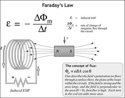
The Windbelt is a direct application of Faraday's Law as shown above. EMF is generated when either pole of a magnet oscillates within close proximity of the core of an inductor coil. Oscillation occurs as a result of wind causing a mylar-coated taffeta band to vibrate, similar to the vibration that occurs when blowing along a blade of grass. If oscillation is of the correct frequency, and there is no torsion in the band, the magnet attached to the band can produce electromagnetic flux at a similar frequency as that of the band.

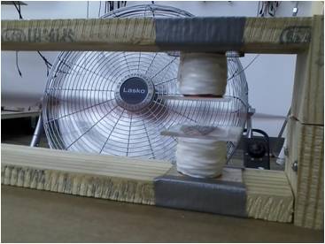
Prototype 5 of the Windbelt included two inductor coils with 1000 windings each, and the band was positioned between them with two magnets fixed to it placed carefully so that they oscillate between the cores of both coils. In theory, this would allow for a larger EMF change over time. The belt produced about 2V AC with the windings connected in series. When connected to a half-wave rectifier, it was able to produce 1.25V DC and 3mA of current. This met the specifications for input signal for the next stage of the power management circuit.
Windbelt Risks
Originally there was risk that the Windbelt would not provide enough voltage due to the nature of the induction coils, and the fact that they were hand wound. This risk has been ruled out, as the Windbelt voltage and current levels have both been measured.
Windbelt Test Plan
- Vary the length of the belt, fan speed, and fan angle to maximize AC current production.
- Test AC/DC rectification component using half-wave and full-wave versions of the circuit, checking for minimal ripple voltage.